Centre of gravity, centroid of areas and equilibrium
Centre of gravity (solid objects)
Gravitational attraction acts on all the particles within a solid, liquid or gas as shown in Fig. 1. It is assumed that the individual particle forces have parallel lines of action. It is further assumed that these individual particle forces can be replaced for calculation purposes by a single, resultant force equal to the sum of the particle forces. The centre of gravity (G) of a solid object is the point through which the resultant gravitational force acts. That is, the point through which the weight of the body acts. For example, the centre of gravity for a cylinder of uniform cross-section lies on the centre line (axis) midway between the two end faces. This and some further examples are shown in Fig. 2.
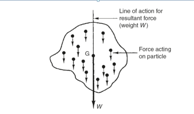
Fig 1
Centre of gravity of non-uniform and composite solids
Fig 3 shows a cylindrical shaft that has two diameters:
- G1 is the centre of gravity of the larger diameter and lies on the axis halfway between the end faces of this diameter.
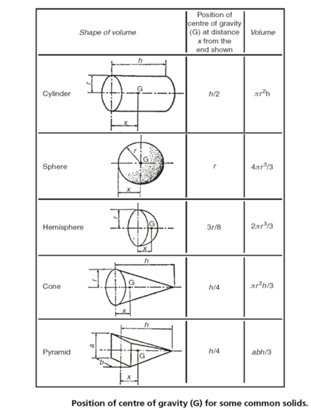
Fig 2
- G2 is the centre of gravity of the smaller diameter and lies on the axis halfway between the end faces of this diameter.
- G is the centre of gravity for the composite solid as a whole and lies at a distance d from the datum end of the shaft. Its position can be determined by the application of the principal of moments.
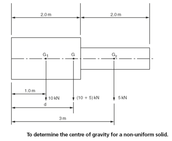
Fig 3
- The overall weight of the shaft is the sum of the weights of the two cylinders. That is,10 kN +5kN=15 kN.
- The total weight of 15 kN will act through the centre of gravity G for the shaft as a whole at some distance d from the datum point P about which moments are taken.
- For this calculation it is conventionally assumed that the moment of G about the point P will be the opposite hand to the moments of G1 and G2 about P, despite the fact that they all appear to produce clockwise moments.
Clockwise moments =anticlockwise moments
(G1 ×1m) +(G2 ×4m) =(G ×d)
(10 kN ×1m) +(5 kN ×3m) = (15 kN ×d)
10 kNm +15 kNm =15 kN ×d
25 kNm =15 kN ×d
Therefore:
d =25 kN m/15 kN =1.67m
The same technique can be used for composite solids where the densities of the various elements differ.
Centre of gravity (lamina)
For a thin sheet metal or rigid sheet plastic component of uniform thickness (a lamina) where the thickness is negligible compared with its area, the centre of gravity can be assumed to lie at the centre of the area:
- For the rectangular lamina the centre of gravity G lies at the point of intersection of the lamina’s diagonals.
- For a circular lamina the centre of gravity G lies at the centre of the circle.
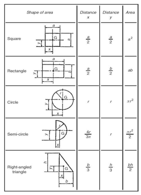
Fig 4
Centroids of areas
The centroid of an area refers to a two-dimensional plane figure that has no thickness. It has only area. Since an area has no thickness it can have no mass to be acted upon by the force of gravity. Therefore it has no weight. The term centroid is applied to the area of a two-dimensional plane figure in much the way that centre of gravity is applied to a solid lamina. Therefore the centroid of an area is the point on a plane figure where the whole area is considered to be concentrated. Like the centre of gravity, the centroid of an area is also denoted by the letter G. Some examples of centroids are shown in Fig. 4.
Equilibrium
Equilibrium was introduced in previoussection. Figure 5(a) also shows that the turning moments acting on each arm of the bar, due to force of gravity, are equal and opposite. Therefore, being perfectly balanced the bar should remain in any position to which it is turned. The bar is said to be in a state of neutral equilibrium. In Fig. 5(b) the same bar is shown pivoted off-centre so that one arm is longer than the other. With the bar upright as shown in Fig. 5(b), the line of action of the vector representing the force of gravity acts through the pivot point and there is no turning moment. However the bar is now in a state of unstable equilibrium since the slightest rotational movement of the bar will cause the centre of gravity to be displaced to one side of the vertical as shown. This will introduce a turning moment that will cause the bar to rotate until the centre of gravity of the longer arm is immediately below the pivot point. There will then be no turning moment and the bar will come to rest. Figure 5(c) shows the bar with the centre of gravity of the longer arm immediately below the pivot point. Therefore there is no moment turning or tending to turn the bar and it will remain stationary. It is also shown that any rotational disturbance of the bar will produce a moment that will cause the bar to rotate until the centre of gravity of the longer arm will again be below the pivot point. Therefore the bar is said to be in a state of stable equilibrium.
Note:
When disturbed, a body will always move or tend to move from a state of unstable equilibrium to a state of stable equilibrium.
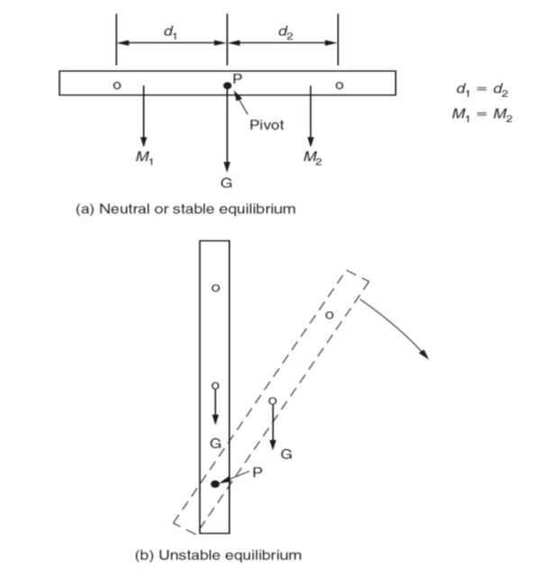
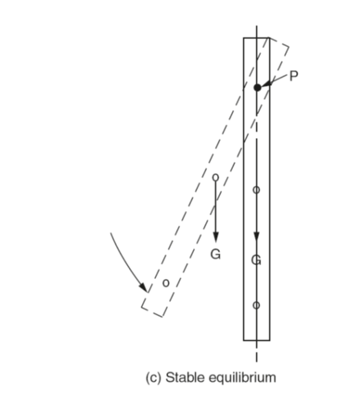
Fig 5: Equilibrium

