
Elasticity
When an external force is applied on a body, which is not free to move, there will be a relative displacement of the particles. Due to the property of elasticity, the particles tend to regain their original position. The external forces may produce change in length, volume and shape of the body. This external force which produces these changes in the body is called deforming force. A body which experiences such a force is called deformed body. When the deforming force is removed, the body regains its original state due to the force developed within the body. This force is called restoring force. The property of a material to regain its original state when the deforming force is removed is called elasticity. The bodies which possess this property are called elastic bodies. Bodies which do not exhibit the property of elasticity are called plastic. The study of mechanical properties helps us to select the material for specific purposes. For example, springs are made of steel because steel is highly elastic.
Stress and strain
In a deformed body, restoring force is set up within the body which tends to bring the body back to the normal position. The magnitude of these restoring force depends upon the deformation caused. This restoring force per unit area of a deformed body is known as stress.
∴ Stress = restoring force/area N m–2
Its dimensional formula is ML–1T–2.
Due to the application of deforming force, length, volume or shape of a body changes. Or in other words, the body is said to be strained. Thus, strain produced in a body is defined as the ratio of change in dimension of a body to the original dimension.
∴ Strain = change in dimension/original dimension
Strain is the ratio of two similar quantities. Therefore it has no unit.
Elastic limit
If an elastic material is stretched or compressed beyond a certain limit, it will not regain its original state and will remain eformed. The limit beyond which permanent deformation occurs is called the elastic limit.
Hooke’s law
English Physicist Robert Hooke (1635 – 1703) in the year 1676 put forward the relation between the extension produced in a wire and the restoring force developed in it. The law formulated on the basis of this study is known as Hooke’s law. According to Hooke’s law, within
the elastic limit, strain produced in a body is directly proportional to the stress that produces it.
(i.e) stress α strain
Stress / Strain = a constant, known as modulus of elasticity.
Its unit is N m-2 and its dimensional formula is ML-1T-2.
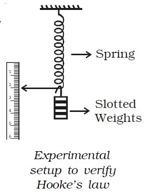
Experimental verification of Hooke’s law
A spring is suspended from a rigid support as shown in the Fig. below. A weight hanger and a light pointer is attached at its lower end such that the pointer can slide over a scale graduated in millimeters. The initial reading on the scale is noted. A slotted weight of m kg is added to the weight hanger and the pointer position is noted. The same procedure is repeated with every additional m kg weight. It will be observed that the extension of the spring is proportional to the weight. This verifies Hooke’s law.
Study of stress – strain relationship
a wire be suspended from a rigid support. At the free end, a weight hanger is provided on which weights could be added to study the behaviour of the wire under different load conditions. The extension of the wire is suitably measured and a stress – strain graph is plotted as in Fig. below.
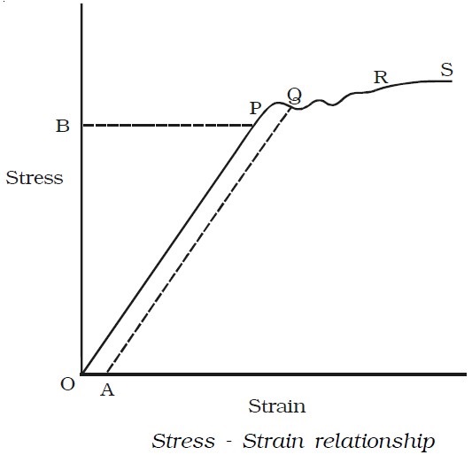
● In the figure the region OP is linear. Within a normal stress, strain is proportional to the applied stress. This is Hooke’s law. Upto P, when the load is removed the wire regains its original length along PO. The point P represents the elastic limit, PO represents the elastic range of the material and OB is the elastic strength.
● Beyond P, the graph is not linear. In the region PQ the material is partly elastic and partly plastic. From Q, if we start decreasing the load, the graph does not come to O via P, but traces a straight line QA. Thus a permanent strain OA is caused in the wire. This is called permanent set.
● Beyond Q addition of even a very small load causes enormous strain. This point Q is called the yield point. The region QR is the plastic range.
● Beyond R, the wire loses its shape and becomes thinner and thinner in diameter and ultimately breaks, say at S. Therefore S is the breaking point. The stress corresponding to S is called breaking stress.
Three moduli of elasticity
Depending upon the type of strain in the body there are three different types of modulus of elasticity. They are
● Young’s modulus
● Bulk modulus
● Rigidity modulus
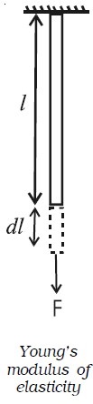
Young’s modulus of elasticity
Consider a wire of length l and cross sectional area A stretched by a force F acting along its length. Let dl be the extension produced.
∴ Longitudinal stress = Force/Area = F/A
Longitudinal strain = change in length/ original length = dl/l
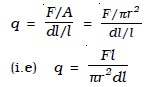
Young’s modulus of the material of the wire is defined as the ratio of longitudinal stress to longitudinal strain. It is denoted by q.
Young’s modulus = longitudinal stress/longitudinal strain
(i.e) q = F/A dl/l or q = F l/A dl
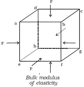
Bulk modulus of elasticity
Suppose euqal forces act perpendicular to the six faces of a cube of volume V as shown in Fig. below. Due to the action of these forces, let the decrease in volume be dV.
Now, Bulk stress = Force/Area = F/A
Bulk Strain = change in volume/original volume = −dV/V
(The negative sign indicates that volume decreases.)
Bulk modulus of the material of the object is defined as the ratio bulk stress to bulk strain.
It is denoted by k.
∴ Bulk modulus = Bulk stress/Bulk strain
(i.e) k = (F/A)/(-dv/v) = P/(-dv/v) [∵P=F/A] or k = -PV/dV
Rigidity modulus or shear modulus
Let us apply a force F tangential to the top surface of a block whose bottom AB is fixed, as shown in Fig. below.
Under the action of this tangential force, the body suffers a slight change in shape, its volume remaining unchanged. The side AD of the block is sheared through an angle θ to the position AD’.
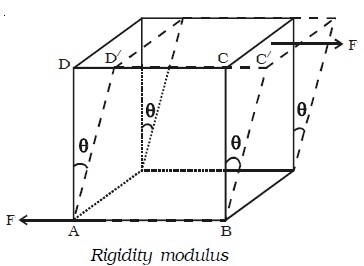
If the area of the top surface is A, then shear stress = F/A. Shear modulus or rigidity modulus of the material of the object is defined as the ratio of shear stress to shear strain. It is denoted by n.
Rigidity modulus = shear stress/shear strain
(i.e) n = F /A / θ
= F/Aθ
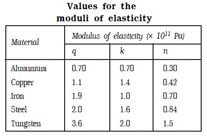
Table above lists the values of the three moduli of elasticity for some commonly used materials.
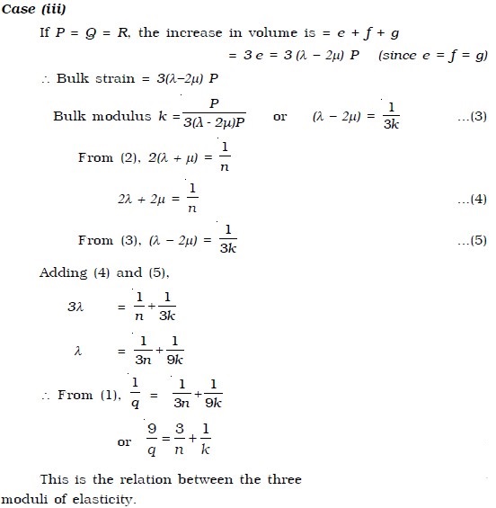
Relation between the three moduli of elasticity
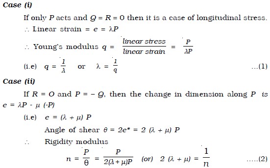
Suppose three stresses P, Q and R act perpendicular to the three faces ABCD, ADHE and ABFE of a cube of unit volume (Fig. below). Each of these stresses will produce an extension in its own direction and a compression along the other two perpendicular directions. If λ is the extension per unit stress, then the elongation along the direction of P will be λP. If μ is the contraction per unit stress, then the contraction along the direction of P due to the other two stresses will be μQ and μR.
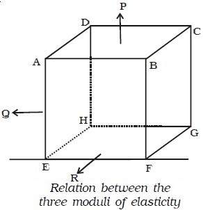
∴ The net change in dimension along the direction of P due to all the stresses is e = λP – μQ – μR.
Similarly the net change in dimension along the direction of Q is f = λQ – μP – μR and the net change in dimension along the direction of R is g = λR – μP – μQ.
Determination of Young’s modulus by Searle’s method
The Searle’s apparatus consists of two rectangular steel frames A and B as shown in Fig. below. The two frames are hinged together by means of a frame F. A spirit level L is provided such that one of its ends is pivoted to one of the frame B whereas the other end rests on top of a screw working through a nut in the other frame. The bottom of the screw has a circular scale C which can move along a vertical scale V graduated in mm. This vertical scale and circular scale arrangement act as pitch scale and head scale respectively of a micrometer screw.
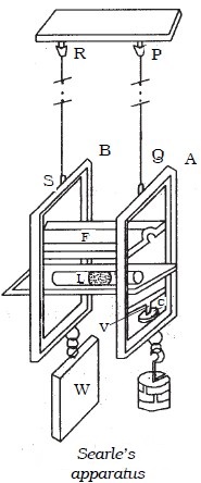
The frames A and B are suspended from a fixed support by means of two wires PQ and RS respectively. The wire PQ attached to the frame A is the experimental wire. To keep the reference wire RS taut, a constant weight W is attached to the frame B. To the frame A, a weight hanger is attached in which slotted weights can be added.
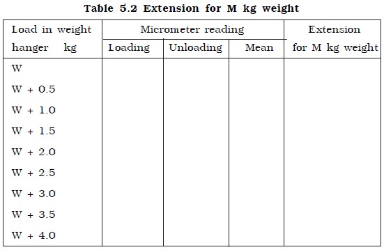
To begin with, the experimental wire PQ is brought to the elastic mood by loading and unloading the weights in the hanger in the frame A four or five times, in steps of 0.5 kg. Then with the dead load, the micrometer screw is adjusted to ensure that both the frames are at the same level. This is done with the help of the spirit level. The reading of the micrometer is noted by taking the readings of the pitch scale and head scale. Weights are added to the weight hanger in steps of 0.5 kg upto 4 kg and in each case the micrometer reading is noted by adjusting the spirit level. The readings are again noted during unloading and are tabulated in Table below. The mean extension dl for M kg of load is found out.
If l is the original length and r the mean radius of the experimental wire, then Young’s modulus of the material of the wire is given by
Applications of modulus of elasticity
Knowledge of the modulus of elasticity of materials helps us to choose the correct material, in right dimensions for the right application. The following examples will throw light on this.
● Most of us would have seen a crane used for lifting and moving heavy loads. The crane has a thick metallic rope. The maximum load that can be lifted by the rope must be specified. This maximum load under any circumstances should not exceed the elastic limit of the
material of the rope. By knowing this elastic limit and the extension per unit length of the material, the area of cross section of the wire can be evaluated. From this the radius of the wire can be calculated.
● While designing a bridge, one has to keep in mind the following factors ▸traffic load ▸weight of bridge▸force of winds. The bridge is so designed that it should neither bend too much nor break.