Resultant force – Vector diagrams of forces: graphical solution
Resultant force
Resultant force – Vector diagrams of forces: graphical solution
resultant force – It has already been stated that forces cannot be seen so they cannot be drawn; however, the effect of forces and systems of forces can be represented by vectors. V.
Resultant forces
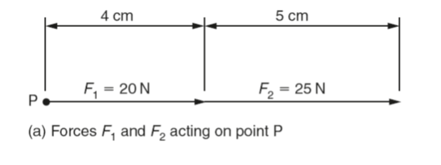
We call a force that can replace two or more other forces and produce the same effect a resultant force. For example, the forces F1 and F2 acting in the same direction on the point P along the same line of action can be replaced by a single force having the same effect as shown in Fig. (a).
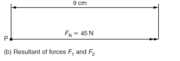
Since both the forces F1 and F2 have a common line of action and act in the same direction, their vector lengths can simply be added together to obtain the magnitude of the vector of the single force that can replace them. This is the force FR shown in the Fig (b).
It is called the resultant force. Note that the vector for a resultant force has a double arrowhead to distinguish it from the other forces acting in the system.
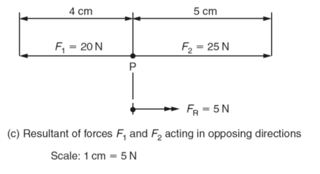
Drawn to a scale of 1 cm =5 N, the vector representing F1 will be 4 cm long and the vector representing F2 will be 5 cm long. When added together to obtain the vector length of the resultant force (FR), this becomes a single vector of 4 cm +5 cm =9 cm long representing a force of 45 N acting at the point P.
(FR) could have been determined by simply subtracting the vector length for F1 from the vector length for F2 as shown in (c).
Parallelogram of forces
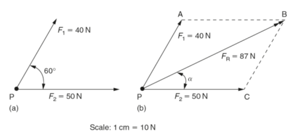
When two or more forces whose lines of action lie at an angle to each other act on a single point P, their resultant force cannot be determined by simple arithmetical addition or subtraction. If only two forces are involved, as shown in below figure, the magnitude and direction of the resultant force can be determined by drawing, to scale, a parallelogram of forces.
(i) Resultant Forces
ii
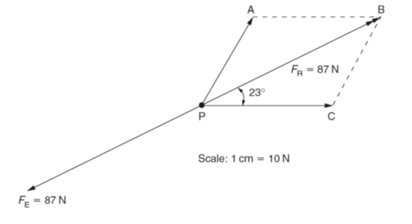
Figure (a) shows the vectors for two forces acting on the point P at an angle of 60° to each other. Figure (b) shows how these vectors form two adjacent sides of a parallelogram PABC. Vector PA represents the force F1 and vector PC represents the force F2. To complete the parallelogram the line AB is drawn parallel to the vector PC and the line CB is drawn parallel to the vector PA. The point B lies at the intersection of the lines AB and CB. The resultant force FR acting at the point P is the diagonal PB of the parallelogram.
The magnitude of the resultant force FR can be determined by measuring the length of the diagonal PB and multiplying it by the scale of the diagram (1 cm =10 N in this instance).
The angle α can be determined by use of a protractor. The values for above diagram are:FR =87 N and α 23° (to the intersection of the lines AB and CB. The resultant force FR acting at the point P is the diagonal PB of the parallelogram.
The magnitude of the resultant force FR can be determined by measuring the length of the diagonal PB and multiplying it by the scale of the diagram (1 cm =10 N in this instance).
The angle α can be determined by use of a protractor. The values for above diagram are:FR =87 N and α 23° (to the nearest whole number).
Equilibrant forces
A force which cancels out the effect of another force or system of forces is called the equilibrant force (FE). An equilibrant force:
- has the same magnitude as the resultant force,
- has the same line of action as the resultant force,
- acts in the opposite direction to the resultant force.
Figure (iii) below shows the equilibrant force (FE) to be equal and opposite to the resultant force (FR), determined in Fig. ii, so that it cancels out the effect of the forces F1 and F2 on the point P.
iii
Resolution of forces
The resolution of forces is the reverse operation to finding the resultant force. That is, the resolution of a force is the replacement of a given single force by two or more forces acting at the same point in specified directions.
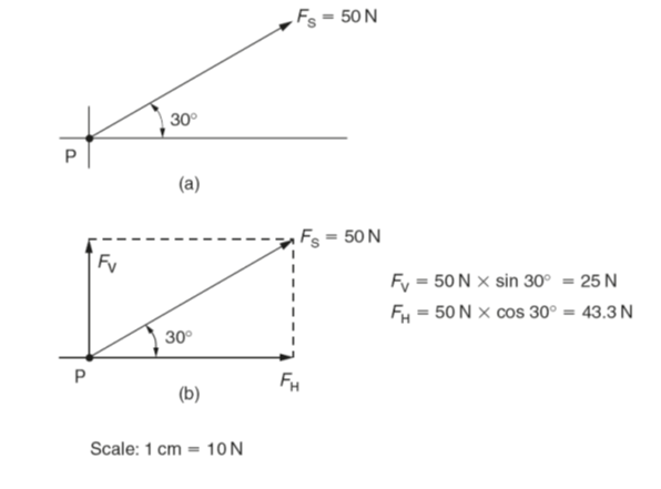
Consider the single force FS of 50 N acting at 30° to the horizontal as shown in Fig. iv(a). To resolve the force into its horizontal and vertical component forces first draw the lines of action of these forces from the point P as shown in Fig. iv(b). Then complete the parallelogram of forces as shown in Fig. iv(b). The magnitude of the forces FV and FH can be obtained by scaling the drawing (vector diagram) or by the use of trigonometry.
(iv) Resultant of forces
Three forces in equilibrium (triangle of forces)
- The vectors of three forces acting in the same plane on a body can be drawn on a flat sheet of paper.
- Forces that act in the same plane are said to be coplanar.
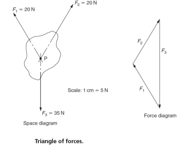
- If the three forces acting on a body are in equilibrium, any one force balances out the effects of the other two forces. The three forces may be represented by a triangle whose sides represent the vectors of those forces.
- If the lines of action of the three forces act through the same point, they are said to be concurrent.
Figure (v) shows three coplanar forces acting on a body. Their lines of action are extended backwards to intersect at the point P. The point P is called the point of concurrency.
(v)
If the forces are in equilibrium:
- Their effects will cancel out.
- The body on which they are acting will remain stationary.
- The vectors of the forces will form a closed triangle.
- The vectors follow each other in a closed loop.
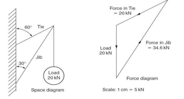
Figure (vi) shows a further worked example. The accuracy of the answers depends on the accuracy of the drawing. This should be as large as possible to aid measurement.
(vi)
Polygon of forces: Bow’s notation
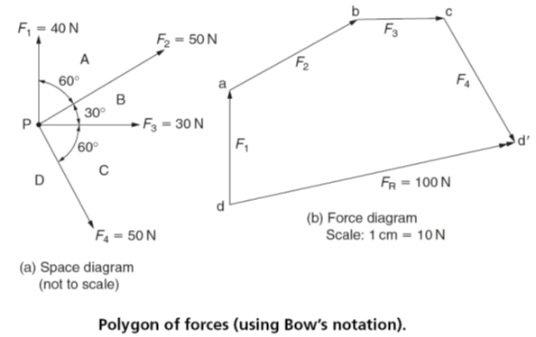
The polygon of forces is used to solve any number of concurrent, coplanar forces acting on a point P. They are concurrent because they act on a single point P. They are coplanar because they lie in the same plane. Figure vii – (a) shows a space diagram with the spaces between the forces designated by capital letters. The corresponding force diagram is shown in Fig. vii – (b) with the forces labelled using lower case letters. This is known as Bow’s notation:
- The forces acting on point P should be represented by vectors whose length and angles must be drawn to scale as accurately as possible. The spaces between the forces are designated using capital letters. The starting point is not important but the lettering must follow round consecutively, usually in a clockwise direction.
- The force diagram must be drawn strictly to scale, starting with a convenient vector. For example, start with the horizontal force F3. Since it lies between the spaces D and A this vector is labelled da. Remember that conventionally the spaces are given capital letters whereas the forces are given the corresponding lower case letters. Add the arrowhead to show the direction in which the force is acting.
- The next force (F4) lies between the spaces A and B. It is drawn to scale following on from the end of the first vector and labelled ab. Again add the arrowhead to indicate the direction in which the force is acting.
- Similarly, add the remaining forces so that they follow on in order labelling them accordingly.
- Finally, the resultant force (FR) can be determined by joining the points and in the force diagram. Note that the direction of the resultant force is against the general flow of the given forces in the force diagram. If required, the resultant force can now be transferred to the space diagram to show its magnitude and direction relative to the point P.
- Remember that the resultant force can replace all the given forces yet still have the same effect on the point P.
- If the equilibrant had been required then it would have the same magnitude as the resultant force but it would act in the opposite direction. It would follow the general flow of the given forces in the force diagram.
-
(vii)
Non-concurrent coplanar forces
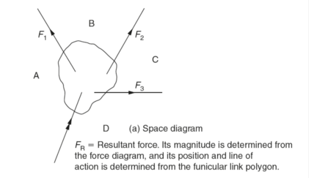
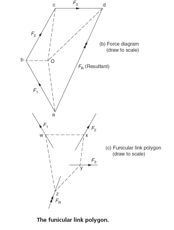
As their name implies, non-concurrent coplanar forces lie in the same plane but do not act at a single point (point of concurrency). An example is shown in Fig. viii(a). Applying Bow’s notation to the space diagram, the resultant force (FR) can be determined from the force diagram in the usual way as shown in Fig. viii(b). However before the position and line of action of the resultant force can be determined it is necessary to construct a funicular link polygon as shown in Fig. viii(c) as follows:
- Draw the force diagram (Fig.viii(b)) in the usual way, and obtain the magnitude and direction of the resultant force (FR) as given by the line ad.
- Choose the pole-point O so that it lies inside or outside the force diagram and join the pole-point O to each corner of the force diagram as shown in Fig. viii(b). The position of the pole-point O is not critical and can be placed wherever it is most convenient.
- From any point w in the line of action of force F1 draw a line in space A parallel to the line Oa in the force diagram. This line is shown in Fig. viii(c).
- From the point w draw the line wx in space B parallel to the line Ob in the space diagram and cutting the force F2 at the point x. This line can be found in Fig. viii(c). It may be necessary to produce the lines of action of the forces to get the necessary intersection.
- Continue with this construction until the lines have been drawn in all the spaces, the space should now resemble Fig. viii(c). The lines parallel to Oa and Od can now be produced until they meet at z. Through z draw a line parallel to ad in the force diagram to represent the line of action of the vector of the resultant force FR.
Note, although the resolution of forces and systems of forces by graphical methods is simple and straightforward, the accuracy depends on the scale of the drawing and the quality of the draughtsmanship. Where more accurate results are required they can be obtained by mathematical calculation using trigonometry.
viii

