
Beam Analysis
Beam Analysis – Shearing force
Beam Analysis – For equilibrium in a beam the forces to the left of any section such as X as shown in Fig. 1(a) must balance the forces to the right of the section X. Also the moments about X of the forces to the left must balance the moments about X of the forces to the right.
Although, for equilibrium, the forces and moments cancel each other, the magnitude and nature of these forces and moments are important as they determine both the stresses at X, and the beam curvature and deflection. The resultant force to the left of X and the resultant force to the right of X (forces or components of forces transverse to the beam) constitute a pair of forces tending to shear the beam at this section. The shearing force is defined as the force transverse to the beam at any given section tending to cause it to shear at that section.
By convention, if the tendency is to shear as shown in Fig. 1(b), the shearing force is regarded as positive (i.e. +F); if the tendency to shear is as shown in Fig. 1(c), it is regarded as negative (i.e. –F).
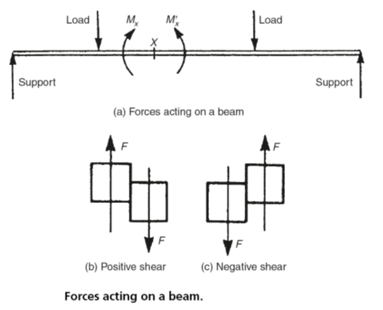
Fig. 1
Bending moment
The bending moment at a given section of a beam is defined as the resultant moment about that section of either all the forces to the left of the section or of all the forces to the right of the section. In Fig. 1(a) the bending moment is either Mx or M’x. These moments will be clockwise to the left of the section and anticlockwise to the right of the section. They will cause the beam to sag. By convention this sagging is regarded as positive bending. That is, positive bending moments produce positive bending (sagging). Similarly negative bending moments cause the beam to bend in the opposite direction. That is, negative bending moments produce negative bending (hogging). The difference between sagging and hogging is shown in Fig. 2.
Contraflexure is present when both hogging and sagging occurs in the same beam as shown in Fig. 2(c). For the loading shown in Fig. 2(a), the beam will sag between the points B and C, and for the loading shown in Fig. 2(b) the beam will hog between the points A and B.
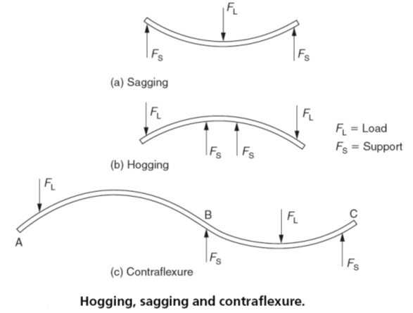
Fig. 2
The values of shearing force and bending moment will usually vary along any beam. Diagrams showing the shearing forces and the bending moments for all sections of a beam are called shearing force diagrams and bending moment diagrams, respectively.
Shearing forces and shearing force diagrams are less important than bending moments and bending moment diagrams; however, they are useful in giving pointers to the more important aspects of a bending moment diagram. For example, wherever the shearing force is zero, the bending moment will be at a maximum or a minimum.
Shearing force and bending moment diagrams
Consider the shearing force and bending moment diagrams for the system of forces acting on the beam in Fig. 3. For the moment, only a simple system of three point loads will be considered.

Fig 3
It is first necessary to calculate the reactions at A and B as previously described in Section. The beam is simply supported at A and B. This means that it rests on supports at these points giving vertical reactions. The general conditions for equilibrium require that the resultant moment about any point must be zero, and the sum of the upward forces must equal the sum of the downward forces. Therefore, taking moments about A, the moment for RB must balance the moment for the load C:
RB ×8m =24 kN ×5m
RB =(24 kN ×5 m)/8m
RB =15 kN
Similarly:
RA =24 kN -15 kN =9kN
Immediately to the right of A the shearing force is due to RA and is therefore 9 kN. As this force is to the left of the section considered it is upwards, hence the shearing force is positive. The shearing force will be constant for all points between A and C as no other forces are applied to the beam between these points.
When a point to the right of C is considered, the load at C as well as the reaction force RB must be taken into account. Alternatively RB on its own can be considered. The shearing force will be 15 kN. This is the value previously calculated for RB or it can be calculated from the load C-RA=24 kN -9kN =15 kN. For any point between C and B the force to the right is upwards and the shearing force is therefore negative as was shown earlier in Fig. 1. It should be noted that the shearing force changes suddenly at point C. This is shown in Fig. 4(a).
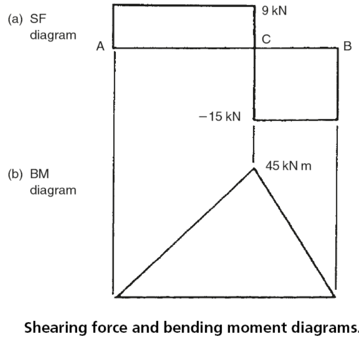
Fig 4
The corresponding bending moments are shown in Fig. 4(b). The bending moment at A is zero, since there are no forces to the left of point A. At a point 1 m to the right of point A the moment of the only force RA to the left of this point is RA ×1m =9 kN m. As this moment about A is clockwise the moment is positive (+9 kN m). At points 2, 3, 4 and 5 m to the right of A the bending moments are respectively:
RA ×2m =9kN ×2m=18 kNm
RA ×3m =9kN ×3m =27 kNm
RA ×4m =9kN ×4m =36 kNm
RA ×5m =9kN ×5m =45 kNm
Since all these are clockwise moments they are all positive bending moments. For points to the right of C, the load at C as well as RA must be considered or, more simply, as previously demonstrated RB alone can be used. At points 5, 6 and 7 m from A, the bending moments are respectively:
RB ×3m =15 kN ×3m =45 kNm
RB ×2m =15 kN ×2m = 30 kNm
RB ×1m =15 kN ×1m =15 kNm
As these moments to the right of the points considered are anticlockwise, they are all positive bending moments. At B the bending moment is zero as there is no force to its right.
The results are summarized in Table 1
| Table 1 Shearing force and bending moment values for Fig.4 | ||||||||||
| Distance from A(m) | 0 | 1 | 2 | 3 | 4 | 5 | 6 | 7 | 8 | |
| Shearing Force (kN) | +9 | +9 | +9 | +9 | +9 | +9 | -15 | -15 | -15 | -15 |
| Bending Moment (kNm) | 0 | +9 | +18 | +27 | +36 | +45 | 30 | +15 | +15 | |
Using the results from Table 1 the shear force and bending moment diagrams can be drawn as shown in Fig. 5. A stepped shearing force diagram with only horizontal and vertical lines can only exist when the beam only carries concentrated, point loads. A sudden change in shearing force occurs where the concentrated loads, including the reactions at the supports, occur. For this type of simple loading the bending moment diagram also consists of straight lines, usually sloping. Sudden changes of bending moment cannot occur except in the unusual circumstances of a moment being applied to a beam as distinct from a load.
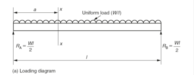
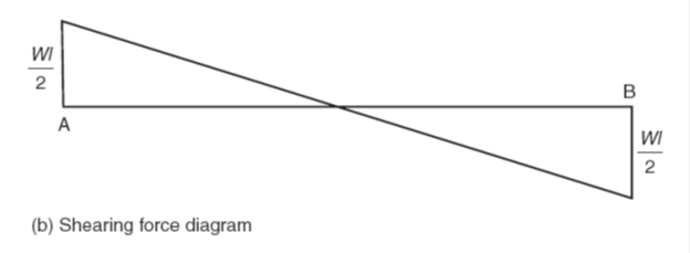
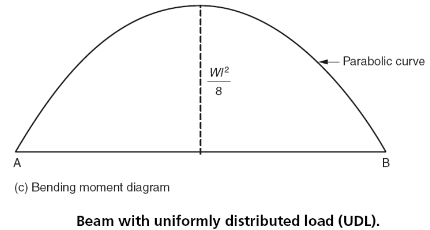
Fig 5
In practice a beam loaded with concentrated point loads alone cannot exist. This is because the beam itself has mass and, therefore, weight. In a beam of uniform cross-section this represents a uniform load throughout the length of the beam. The effect of uniform loading will now be considered.
Figure 5(a) shows a uniformly loaded beam of length l and weight W. The only point loads being the reactions at the supports RA and RB. Since the loading is symmetrical RA and RB will both equal W/2. The shear force diagram shows maximum values at the points of support and zero shear at the midpoint. This time, however, the line joining the shearing force is a sloping line passing through the midpoint.
Take a section XX at a distance a from the left-hand support RA:
The shearing force at XX =(Wl/2) -(W× a)
Since this is the equation of a straight line the shear force diagram is shown in Fig. 5(b). Unlike the previous example, this time the bending moment diagram is not made up of straight lines but is a continuous curve with a maximum value at the midpoint.
The bending moment Mx at XX =[(Wl/2) ×a] – [W ×a × (a/2)]
Therefore:
Mx=W/2(la–a2) (1)
This is the equation of a parabola so, its first derivative will be a maximum when:
dMx/da = 0
Differentiating equation (1):
dMx/da =W/2(l -2a) =0
When:
a =l/2
The maximum bending moment occurs at the centre of the span which is only to be expected with symmetrical loading. Hence substituting a =l/2 in equation (1):
Mmax =W/2[(l2/2) -(l2/4)] =Wl2/8
The bending moment diagram is shown in Fig. 5(c). Apart from the beam shown in Fig. 5(a) where the uniform load resulted from gravity acting on the mass of the beam itself, the only other occasion when a beam is uniformly loaded is when it is carrying a uniform panel of masonry.
More often, there is a combination of point loads and uniform loading as shown in the loading diagram Fig. 6(a).
(a) Calculate reactions RA and RC by taking moments about A:
(45 ×2) +(12 ×9) ×4.5 +(24 ×12) =9RC
Thus: RC =96 kN and RA =81 kN
(b) Shearing forces (let x be any distance from A):
For 0 ≤x≤ 2, shear force =(81 – 12x) kN
For 2 ≤x≤ 9, shear force =(81 – 12x – 45) = (36-12x) kN
For 9 ≤x ≤12, shear force= (81-12×9-45+96)=+24 kN
These results are depicted by straight lines as shown in Fig. 6(b)

Fig 6
(c) Bending moments (let x be any distance from A):
For 0 ≤x ≤2, M =81x-12(x2/2) =81x-6x2kNm
Therefore: at A, x =0 and MA =0
at B, x =2 and MB=162-24=138 kNm
For 2 ≤x ≤9, M =81x – (12x2/2) – 45 (x-2)=36x-6x2+90 kNm (2)
At x =2 MB =72-24+90= 138 kN m (as above)
At x=9 MC =324-486+90 =-72 kNm
The maximum bending moment occurs between the points B and C where dM/dx= 0.
Note this is the same point that the shearing force is also zero. From equation (2):
dM/dx =36-12x=0
Therefore:
x =3m
Substituting x=3 in equation (2):
(36 ×3)-(6×32)+90=144 kN m.
Thus the maximum bending moment is 144 kN m and it occurs at a point 3 m from A. Contraflexure will occur when the bending moment is zero. That is, the positive root of equation (2) when it is equated to zero.
36x-6x2+90=0
Therefore:
x =7.9m (the only positive solution)
Therefore contraflexure occurs at a point 7.9 m from A.
Beams (cantilever)
As well as being simply supported as in the previous examples, beams may also be in the form of a cantilever. That is, only one end of the beam is supported and the remote end from the support is unsupported as shown in Fig. 7(a). The supported end of the beam may be built into masonry or it may be a projection from a simply supported beam. A typical shearing force diagram and a typical bending moment diagram for a cantilever beam with concentrated, point loads are shown in Fig. 7(b) and (c).
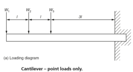
Fig. 7
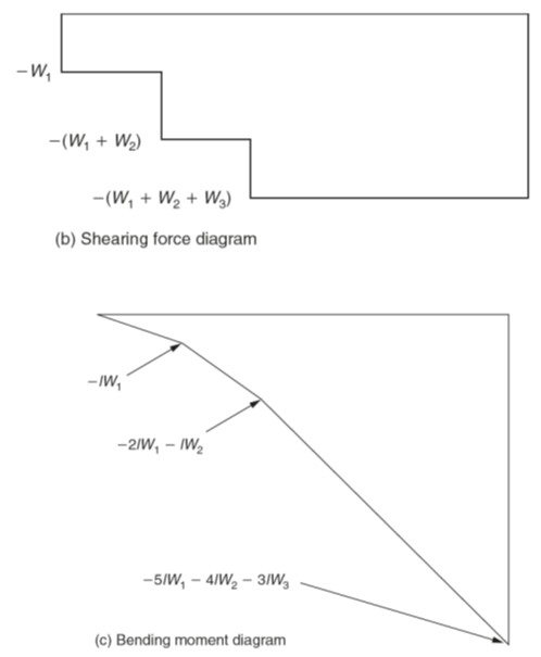
Fig. 8