
Moments of forces, centre of gravity and centroids of areas
Moments forces
Moments forces – Figure 1 (a) shows how a spanner is used to turn a nut. The force (F) is not acting directly on the nut but a distance (d) from the axis of the nut. This produces a turning effect called the moment of the force about the axis of the nut. It is also called the turning moment or couple but all these terms mean the same thing. The distance (d) is called the moment arm or the leverage distance, both terms being interchangeable. Expressed mathematically:
M =F × d
where:
M = moment of the force (Nm)
F = the applied force (N)
d = the moment arm (leverage distance) (m)
Note: It is essential that the moment arm (d) is measured perpendicularly to the line of action of the force. If the force is inclined as shown in Fig. 1(b) the effective length of the spanner is shortened. The equation becomes:
M =F ×de
where:
M= moment of the force (Nm)
F = the applied force (N)
de =the effective moment arm (leverage distance) (m)
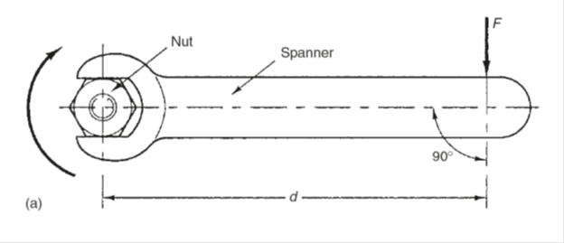
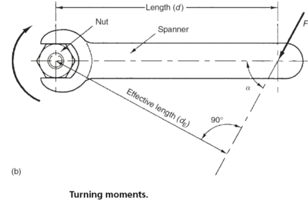
Fig 1
Principle of moments (related terminology) – Moments forces
Fulcrum = The pivot point or axis about which rotation takes place or tends to take place.
Moment arm = The distance between the line of action of an applied force and the fulcrum point measured at right angles to the line of action of the force.
Clockwise moment=Any moment of a force that rotates or tends to rotate a body about its fulcrum in a clockwise direction. Clockwise moments are considered to be positive (+) as shown in Fig. 2
Anticlockwise moment= Any moment of a force that rotates or tends to rotate a body about its fulcrum in an anticlockwise direction. Anticlockwise moments are considered to be negative (-) as shown in Fig. 2.
Resultant moment= This is the difference in magnitude between the total clockwise moments and the total anticlockwise moments.
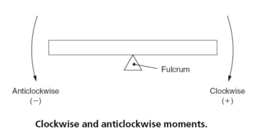
Fig. 2
Principle of moments
The algebraic sum of the moments of a number of forces acting about any point is equal to the resultant moment of force about the same point.
Expressed mathematically:
MR =M1+M2+(-M3)+ … +Mn
where:
MR =the resultant moment of force
M1 to Mn = any number of moments acting about the same fulcrum point
Remember: The positive moments will be acting in a clockwise direction, whereas the negative moments (such as –M3) will be acting in an anticlockwise direction.
Fig. 3
Applying the above principles to the lever in Fig. 3(a), calculate:
(a) The magnitude of the resultant force.
(b) The magnitude of the resultant moment.
(c) The position of the line of action of the resultant force.
(a) Since the lines of action of the applied forces acting on the lever shown in Fig. 3(a) are parallel to each other, the resultant force (FR) can be obtained by simple addition and subtraction:
- Forces F1 and F2 tend to move the lever upwards. They are acting in the same direction; therefore they can be added together.
- Force F3 acts in the opposite direction, therefore it is subtracted from the sum of F1 and F2.
Therefore:
FR =F1+ F2 +F3
=25 N +40 N -50 N
=15N
(b) To find the magnitude of the resultant moment (MR)
Clockwise moments (+):
M1 =F1 × (2m +2m) = 25 N× 4m =100Nm
M2 =F2 ×2m= 40 N× 2m= 80Nm
Anticlockwise moments (-):
M3 =F3 ×3m =50 N ×3m = 150Nm
Resultant moment:
MR = M1 +M2 –M3= 100Nm+80Nm-150Nm
= 30Nm
(c) To combine the results of (a) and (b) in order to find the position of the line of action of the resultant force (FR), refer to Fig. 3(b).
MR =FR ×d =30Nm
Therefore:
30Nm =15 N×d
d =30 Nm/15 N = 2m
Therefore the forces F1, F2 and F3 can be replaced by the single force FR acting at a point 2 m from the fulcrum. Since MR is positive the force FR will move or tend to move the lever in a clockwise direction so the force FR will act in an upwards direction as shown.
Equilibrium
In the previous section, the moments have not acted in equal and opposite directions. This has resulted in a residual, resultant force, causing or tending to cause a rotation about a pivot point (fulcrum).
Fig.4 shows a simple balance scale in which the masses M1 and M2 in the scale pans are of equal magnitude so that the scales balance and the beam is horizontal. Since the force of gravity acts equally on M1 and M2, the forces F1 and F2 are also equal. The reaction force (R) equals the sum of the downward forces.
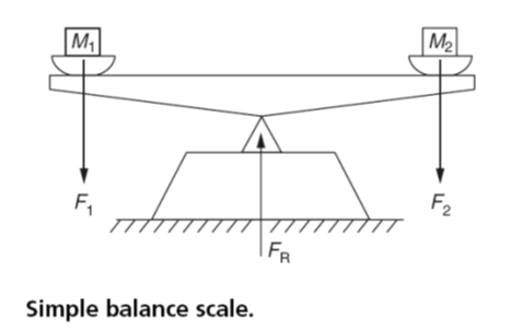
Fig. 4
The forces are equidistant from the fulcrum, so the turning moments are also equal. Since the turning moments act in opposite directions these moments are also in equilibrium. They balance each other and there is no tendency for the scale-beam to rotate. This can be summarized as follows:
When a body is in a state of equilibrium (balance) under the action of a number of forces, the clockwise moments about any point is equal to the anticlockwise moments about the same point.
Put more elegantly:
The algebraic sum of the moments about any point is zero.
For a body to be in a state of equilibrium the following conditions must exist:
- The algebraic sum of the horizontal forces acting on the body must equal zero, ∑FH=0.
- The algebraic sum of the vertical forces acting on the body must equal zero, ∑FV =0.
- The algebraic sum of the moments acting on the body must equal zero, ∑M= 0.
Fig. 5 shows a lever pivoted at its centre. The line of action of a force F1 is 2 m to the left of the pivot and tends to impart an anticlockwise moment.
The line of action of force F2 is 3 m to the right of the pivot and tends to impart a clockwise moment. If the magnitude of F2 is 20 N, calculate:
- The magnitude of the force F1 required to put the lever into a state of equilibrium.
- The magnitude of the reaction force (FR) at the pivot.
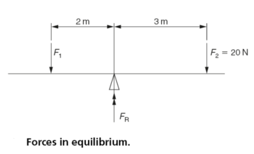
Fig. 5
For equilibrium:
Clockwise moments = anticlockwise moments
(20 N ×3m) =(F1× 2m)
F1 =(20 N ×3 m)/2m =30N
The reaction force FR, acting upwards, is equal and opposite to the sum of F1 and F2 acting downwards. Therefore:
R =F1+ F2 =20 N +30 N =50N
Fig. 6 shows a simple beam supported at each end. Since it is in equilibrium there is no tendency for it to rotate and the reaction forces RA and RB at the supports can be calculated using the principle of moments. This is achieved by taking moments about each support in turn.
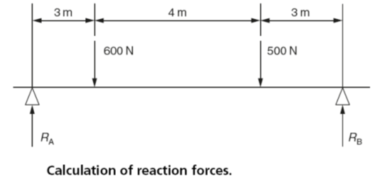
Fig. 6
To determine the magnitude of RA take moments about RB in order to eliminate it from the initial calculation so that only one unknown quantity has to be calculated as follows:
Clockwise moments = anticlockwise moments
RA × 10m = (600 N ×7m) + (500 N ×3m)
RA × 10m =4200Nm + 1500Nm
RA × 10m =5700Nm
RA =5700 Nm/10m
RA = 570N
Similarly to determine the magnitude of RB take moments about RA in order to eliminate it from the initial calculation so that only one unknown quantity has to be calculated as follows:
Clockwise moments =anticlockwise moments
(600 N×3m)+(500 N ×7m)=RB×10m
1800Nm+3500Nm= RB×10m
5300Nm =RB ×10m
RB ×5300 Nm/10m
RB =530N
For a system of forces in equilibrium the downward forces must equal the upward forces.
Therefore:
RA +RB =600 N +500 N
570 N +530 N =600 N +500 N
1100 N =1100 N
which is true. Therefore the calculation for RA and RB are correct. Avoid taking the shortcut of calculating on one of the reaction forces and deducting it from the sum of the downward forces. Any error in the initial calculation will be carried forward and no check will be possible.
The above examples ignore the weight of the beam.
The weight of a uniform beam may be considered to be a concentrated force whose line of action can be assumed to act through the centre of the length of the beam.