
Direct Stress and Strain
Direct Stress and Strain
Figure 1 (a) shows a cylindrical bar of cross-sectional area A in tension, whilst Fig. 1 (b) shows the same bar in compression. The applied forces F are in line and are normal (perpendicular) to the cross-sectional area of the bar. Therefore the bar is said to be subject to direct stress. Direct stress is given the symbol σ (Greek letter sigma).
Direct stress σ= applied force F/cross-sectional area A
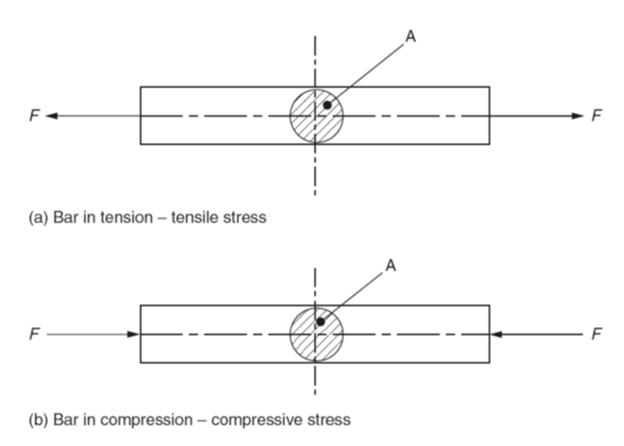
Fig 1: Direct Stress
Shear stress
Figure 2 shows a riveted joint. Since the applied forces Q are offset (not in line) the rivet is said to be subjected to shear stress which is given the symbol τ (Greek letter tau).
Shear stress τ = shear force Q/area in shear A
Direct stress and shear stress are usually of sufficient magnitude to be measured in MN/m2
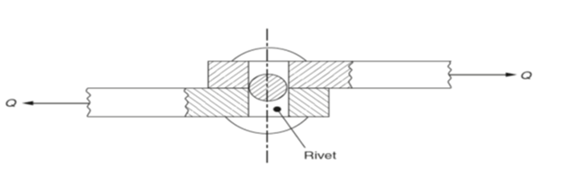
Fig 2. Shear (Indirect) Stress
Direct strain
The forces acting on a body that produce direct stress also cause a change in the dimensions of that body. For example, a tensile load will produce tensile stress and also cause the body to stretch as shown in Fig. 3(a). Similarly, a compressive load causes the body to shorten as shown in Fig. 3(b). Direct strain is given the symbol ε (Greek letter epsilon).
Direct strain ε = change in length xloriginal length l
Since both the change in length and the original length are measured in the same units, strain is a ratio and has no units.
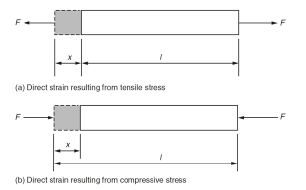
Fig 3. Direct Strain
Shear strain
Shear strain is shown in Fig. 4. The applied forces Q are offset and cause material to deform. Shear strain is given the symbol γ(Greek letter gamma).
Shear strain γ =deformation x/original dimension l
Again this is a ratio so there are no units.
Modulus of elasticity (Hooke’s law)
Hooke’s law states that within the elastic range for any given material, the deformation is proportional to the applied force producing it. When this law is applied to a spring:
Stiffness of the spring = direct stress σ /direct strain ε
The modulus of elasticity E can be derived from Hooke’s law. Stress is directly proportional to strain whilst the material is stressed within its elastic range, thus:
Stress ∝ strain
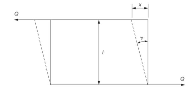
Fig 4. Indirect shear strain
Therefore:
Stress =strain *a constant
Therefore:
Stress/strain =a constant
This constant (symbol E) is called the modulus of elasticity (or Young’s modulus) and is measured in GN/m2.
E =stress σ /strain ε
Modulus of rigidity
The modulus of rigidity G relates to shear strain and shear stress such that:
Modulus of rigidity G =shear stress τ /shear strain γ
The modulus of rigidity is also measured in GN/m2. Table shows the modulus of rigidity and the modulus of elasticity for some typical materials.
| Modulus of elasticity and modulus of rigidity for some typical materials. | ||
| Material |
Modulus of Elasticity (E) GN/m2 |
Modulus of rigidity(G) GN/m2 |
| Aluminium | 70 | 26 |
| Brass(70/30) | 101 | 37 |
| Cadmium | 59 | 19 |
| Chromium | 279 | 115 |
| Copper | 130 | 48 |
| Iron (cast) | 152 | 60 |
| Lead | 16 | 6 |
| Steel (mild) | 212 | 82 |
| Tin | 50 | 18 |
| Titanium | 116 | 44 |
| Tungsten | 411 | 161 |
| Zinc | 108 | 43 |
Torsional stress
With reference to Fig. 5, it can be seen that when a shaft of circular cross-section acted on by a torque (turning moment) T:
- All sections of the shaft remain circular and of unchanged diameter.
- Plane cross-sections remain plane (circular only) providing the angle of twist is small.
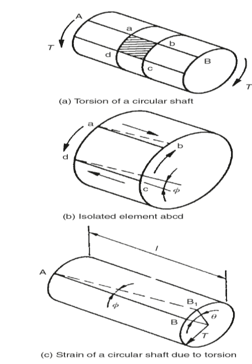
Fig 5: Torsional stress and strain
For the isolated cylindrical element of the shaft, the end faces remain plane and any rectangular surface element abcd will be in a state of pure shear. Shear stresses along ad and bc will induce complementary shear stress along ab and cd. Longitudinal twisting of the shaft occurs so that the lengths ab and cd are sheared through angle φ relative to the line AB.
For pure shear and small angles of twist, angle φ represents shear strain and τ is the shear stress at the surface of the shaft. Since:
Modulus of rigidity G =shear stress/shear strain
and:
Arc BB1= l φ providing φ is small
and:
Arc BB1= rθ
where:
r =the radius of the shaft
θ= the angle of twist over the full length l of the shaft.
Therefore:
l φ =arc BB1 = rθ
φ= rθ/l
Substituting for φ in equation (1):
G = τ/(rθ/l) or τ /r =Gθ/l
Note:
Since G and l are constant for any given shaft and _ is constant for all radii at any particular cross-section then:
τ /r= constant
Thus the shear stress at any point within a given cross-section is proportional to the radius, and the stress increases uniformly from zero at the centre of the shaft to a maximum at the outside radius. For this reason it is apparent that a hollow shaft can transmit a greater torque than a solid shaft of the same cross-sectional area.
Hoop stress in thin cylindrical shells
With reference to Fig. 6 it can be seen that the pressure P tends to increase the diameter of the cylinder. This stretches the cylinder walls circumferentially and sets up a tensile stress known as the hoop stress σ h.
The force due to the internal pressure P is balanced by the hoop stress σ h. Hence:
Hoop stress × area= pressure × projected area
σ h ×2lt = Pdl
σ h= Pd/2t
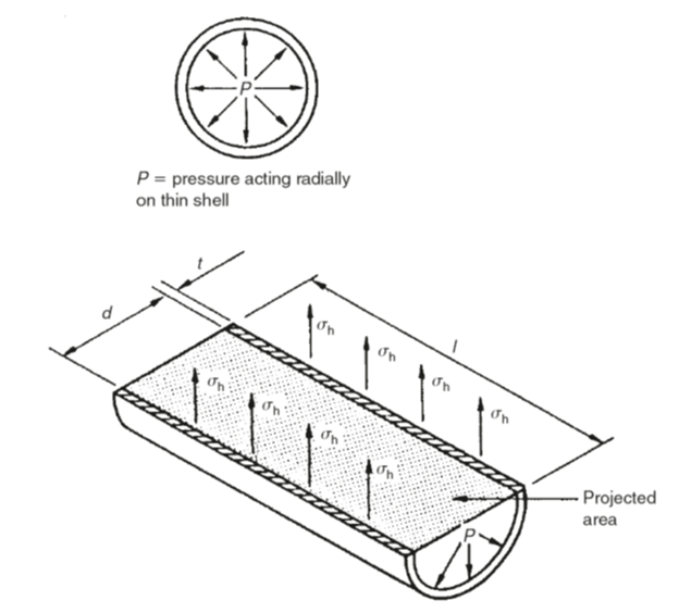
Fig 6. Hoop stress in thin cylindrical shells
Longitudinal stress in thin cylindrical shells
With reference to Fig. 7 it can be seen that the internal pressure P is also a tensile stress in the longitudinal direction known as σ1. Hence the pressure P acting over the area πd2/4 is balanced by the longitudinal stress σ1 acting over the area πdt. (Strictly, the mean diameter should be used but, as the wall thickness t is small compared with the diameter, this approximation is adequate.) Thus:
P × (πd2/4)= σ1 ×πdt
σ1 =(πPd2)/(4πdt)
σ1=Pd/4t
Note:
The equations for σ h and σ l assume stresses are, for all practical purposes, constant over the wall thickness. This is only valid if the ratio of thickness to internal diameter is less than 1:20.
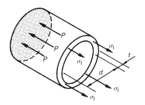
Fig.7. Longitudinal stress in thin cylindrical shells