Weld Type and Weld Joint Configuration
Weld Joint Configuration
Weld Positions
For a welder, it is important to be able to weld in different positions. The American Welding Society has defined the positions of welding to include:
• Flat.
• Horizontal.
• Vertical.
• Overhead.
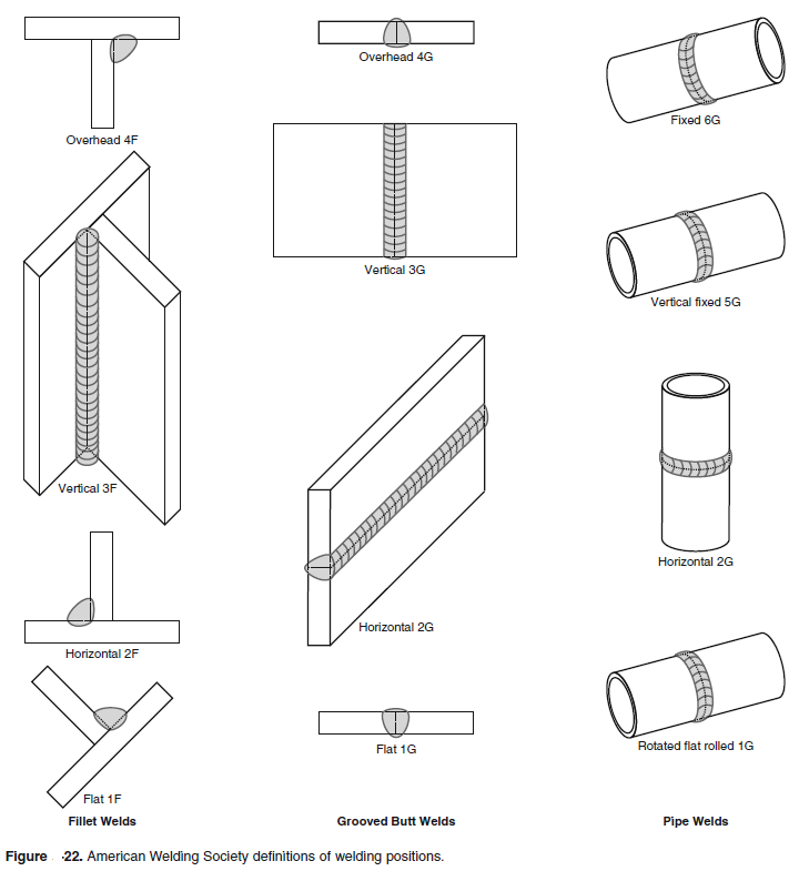
Figure 22 below demonstrates the four positions for fillet welds, grooved butt welds, and pipe welds. While practicing welding in these positions, you should note how
gravity affects the molten weld pools. In addition to this, heat distribution also varies with each position. These factors make the skills needed for each position distinct.
Practice is required to produce good welds in all positions.
Design Considerations
Design of the weld type and weld joint to be used is of prime importance if the weldment is to do the intended job. The weld should be made at reasonable cost. Several
factors concerning the weld design must be considered:
• Material type and condition (annealed, hardened, tempered).
• Service conditions (pressure, chemical, vibration, shock, wear).
• Physical and mechanical properties of the completed weld and heat-affected zone.
• Preparation and welding cost.
• Assembly configuration and weld access.
• Equipment and tooling.
Butt Joints and Welds
Butt joints are used where high strength is required.
They are reliable and can withstand stress better than any other type of weld joint. To achieve full stress value, the weld must have 100 percent penetration through the joint. This can be done by welding completely through from one side. The alternative is working from both sides, with the welds joining in the center.
Thinner-gauge metals are more difficult to fit up for welding. Thin metals also require more costly tooling to maintain the proper joint configuration. Tack welding may be used as a method of holding the components during assembly. However, tack welds present many problems:
• They conflict with penetration of the final weld into the weld joint.
• They add to the crown dimension (height).
• They often crack during welding due to the heat and expansion of the joint.
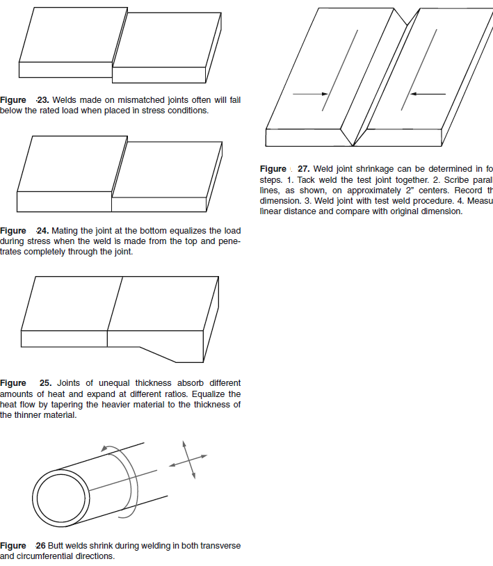
Expansion of the base metal during welding often
will cause a condition known as mismatch, Figure 23. When mismatch occurs, the weld generally will not penetrate completely through the joint. Many specifications
limit highly stressed butt joints to a 10 percent maximum mismatch of the joint thickness.
Whenever possible, butt joints should mate at the bottom, Figure 24. Joints of unequal thickness should be tapered in the weld area to prevent incomplete or inadequate fusion. This is shown in Figure 25. When this cannot be done, the heavier piece may be tapered on the upper part of the joint as well.
Weld shrinkage. Butt welds always shrink across the joint (transversely) during welding. For this reason, a shrinkage allowance must be made if the “after welding”
overall dimensions have a small tolerance. Butt welds in pipe, tubing, and cylinders also shrink on the diameter of the material. This shrinkage is shown in Figure 26.
In areas where these dimensions must be maintained, a shrinkage test must be done to establish the amount of shrinkage. Figure 27 shows how such a test is made.
Heavier materials will shrink more than thinner materials. Double-groove welds will shrink less than single-groove welds. This is because less welding is involved and less filler material is used.
T-Joints and Welds
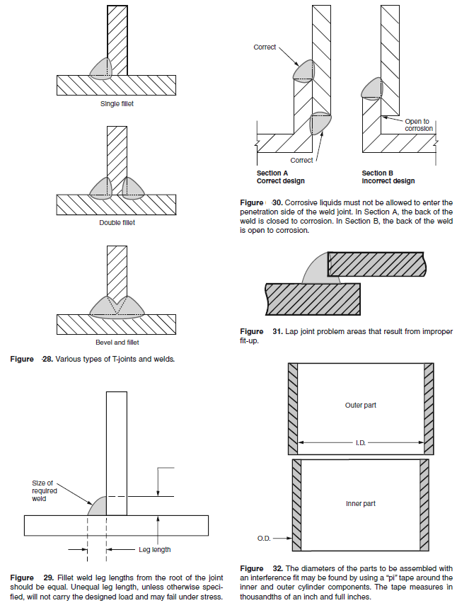
Various T-joint designs are used to join parts at an angle to each other. Depending on the intended use of the weldment, the joint may be made with a single fillet, double fillet, or a groove and fillet weld combination. Figure 28 shows these designs.
Fillet welds are made to specific sizes that are determined by the allowable design load. They are measured as shown in Figure 29. Where design loads are not known, a “rule of thumb” may be used for determining the fillet size. In these cases, the fillet weld leg lengths must equal the thickness of the thinner material.
The main problem in making fillet welds is lack of penetration at the joint intersection. To prevent this condition, always make stringer beads at the intersection.
Weave beads do not provide the desired penetration on fillet welds.
Lap Joints and Welds
Lap joints may be either single fillet, double fillet, plug slot, or spot-welded. They require very little joint preparation. They are generally used in static load applications
or in the repair of unibody automobiles. Where corrosive liquids are involved, both edges of the joint must be welded. See Figure 30. One of the major problems
with lap joint design is shown in Figure 31. Where the component parts are not in close contact, a bridging fillet weld must then be made. This leads to incomplete
fusion at the root of the weld and oversize fillet weld dimensions. When using this type of design in sheet or plate material, clamps or tooling must be used to maintain
adequate contact of the material at the weld joint.
An interference fit eliminates this problem in assembly of cylindrical parts, Figure 32. The inside diameter of the outer part is made several thousandths of an inch smaller than the outside diameter of the inner part. Before assembly, the outer part is heated until it expands enough to slide over the inner part. As the part cools, it shrinks and locks the two pieces together.
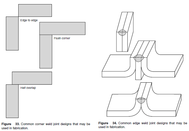
Corner Joints and Welds
Corner joints are similar to T-joints, since they consist of sheets or plates mating at an angle to one another. They are usually used in conjunction with groove welds and fillet welds. Some of the many different corner weld designs are shown in Figure 33. When using thinner gauges of metal, it may be difficult to assemble component parts without proper tooling.
Tack welding and welding often will cause distortion and buckling of thinner materials. For the most part, use of corner joints should be limited to heavier materials in
structural assemblies.
Edge Joints and Welds
Edge welds are used where the edges of two sheets or plates are adjacent and are in approximately parallel planes at the point of welding. Figure 6-34 shows several
types of edge weld designs. These designs are common only in structural use. Since the weld does not penetrate completely through the joint thickness, it should not be
used in stress or pressure applications.